Syncrosnap® Centrifugal Switches
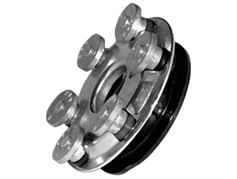
Our core competency is the design and manufacture of centrifugal mechanisms which control the start-winding of single-phase electric motors.
View Syncrosnap® Products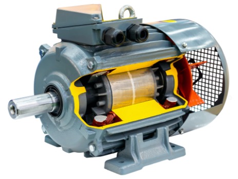
Motor & Switch Replacement Parts
Replacement switches are shipped from stock for quick turn-around for your motor repairs.
View Motor & Switch Replacement Parts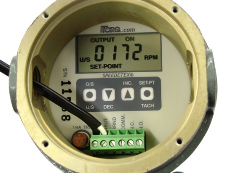
Speedetex Speed Switches
Reliable electro-mechanical and electronic speed responsive switches for measuring speed that's essential for performance and protection.
View Speedetex ProductsAbout Us
70+ Years In Business
Made In America
We’ve become the leader in centrifugal switch design after our founder developed a unique switching mechanism for controlling the auxiliary start-winding of single-phase electric motors.
Our Resources
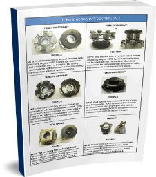
TORQ™ Syncrosnap® Centrifugals
Download Now
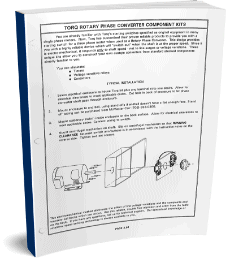
Rotary Phase Converters 1
Download Now
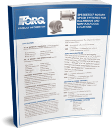
Speedetex Rotary Speed Switch Overview
Download Now

